AC-Link technology

VIDAR’s patented AC-Link technology replaces conventional AC-to-DC-to-AC VFD technology with a streamlined AC-to-AC approach. By removing the DC stage, bulky capacitors are eliminated, shrinking the VFD by 60%, enabling the motor and VFD to be combined into a single, compact solution. 

01

Compact and integrated 

By removing the need for the DC stage, VIDAR shrinks the size of the power converter by 60% compared to comparable VFDs. 


03

Ultra-low harmonics 

VIDAR’s design minimizes harmonic distortion, maintaining power quality in compliance with IEEE-519 standards. 

02

Increased reliability

The elimination of electrolytic capacitors removes a major failure point, resulting in a more durable and long-lasting system.


04

Seamless integration

With its compact design, VIDAR eliminates long cable runs between the VFD and motor, resulting in longer motor insulation life. 
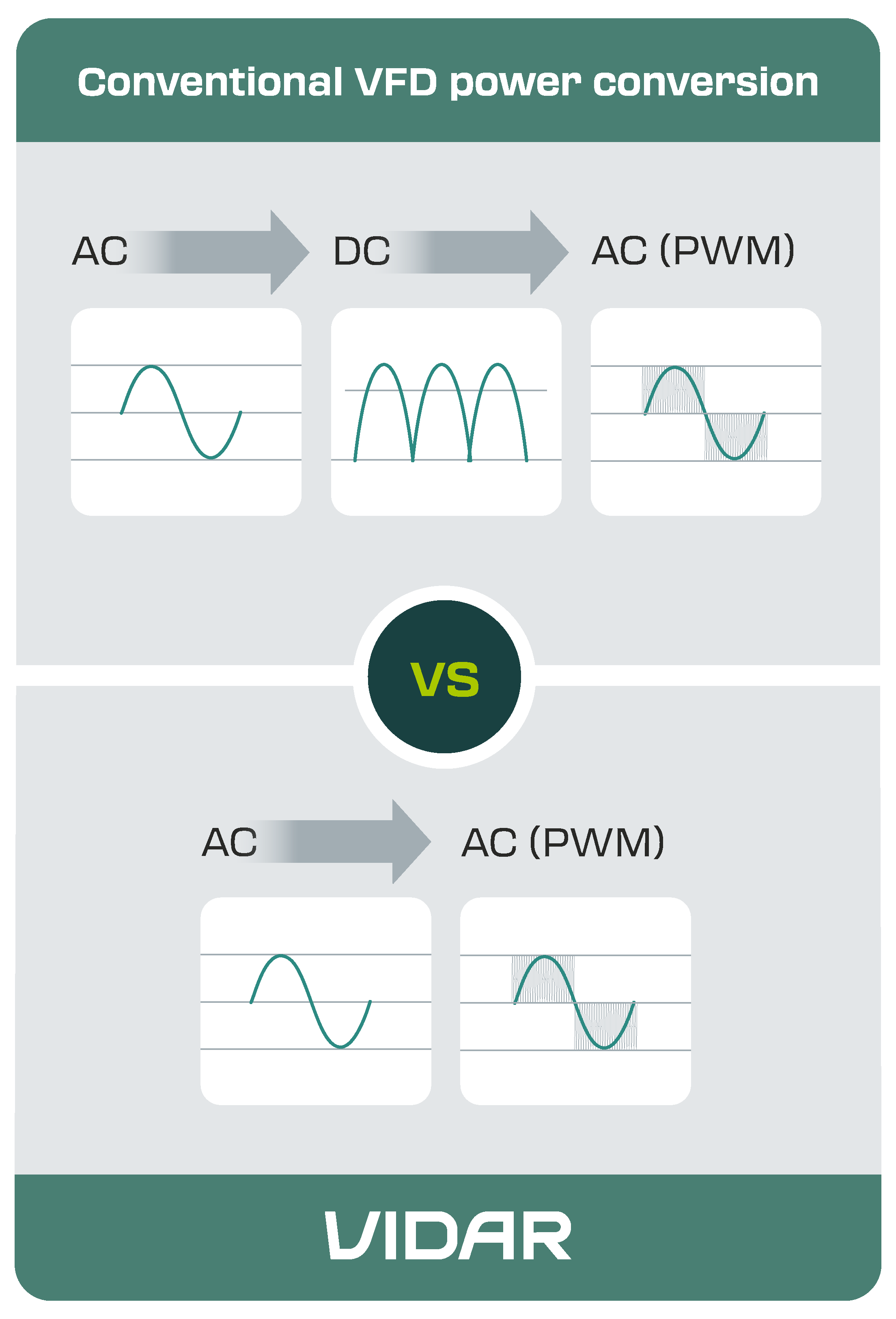
Image alt

Synchronous Reluctance Magnet-Assisted Motor
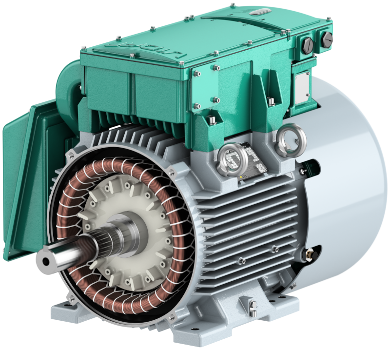
Image alt


VIDAR is purpose-built for industrial facilities. It uses a high-efficiency Synchronous Reluctance Magnet-Assisted motor designed using IEEE-841 specifications, meets CSA Class 1 Division 2 for hazardous areas and meets IEEE-519 power quality standards for dependable performance even in the toughest environments. 

01

Synchronous Reluctance Magnet-Assisted (SRMA) design

The VIDAR motor combines reluctance torque with permanent magnet assistance, eliminating rotor-induced currents for higher efficiency and power density.

02

Lower operating temperature and higher efficiency

Operating 10-25% cooler than induction motors, VIDAR reduces energy losses, extends component lifespan, and enhances reliability.

03

Optimized torque and performance 

Its advanced magnetic design delivers superior efficiency, higher torque, and a better power factor, reducing energy consumption in industrial applications.

Innovation meets durability
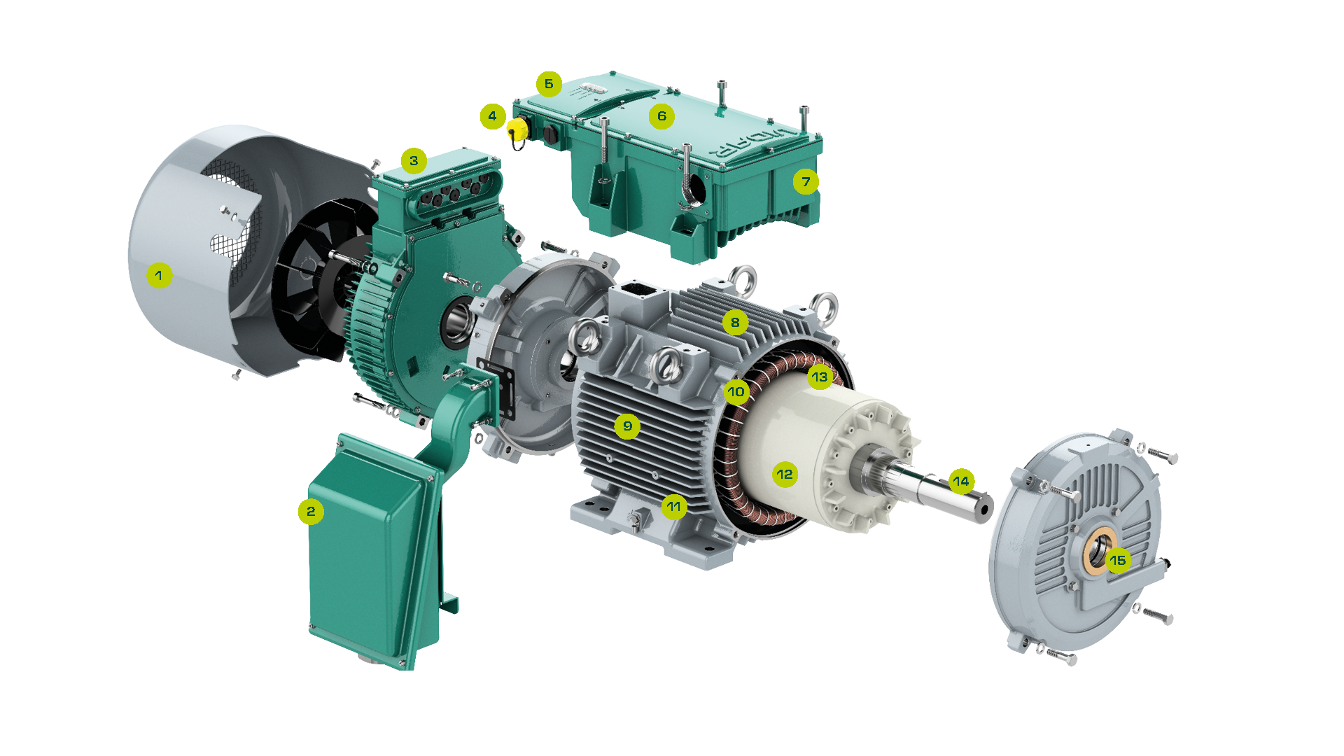
Image alt

1. Fan
Bi-directional, non-sparking, corrosion-resistant conductive plastic material

2. Motor Terminal Box
Standard F3 configuration with optional F1 or F2

3. IP66 AC-Link Converter and Terminal Box
Fully sealed against dust, water, and harsh weather for reliable outdoor operation

4. Hazardous Area Rated
Class 1 Division 2 Groups A, B, C, D T4

5. Safe Torque Off (STO)
Safety integrity level IEC615058
SIL2, ISO 13879-1 Category 3PL d6

6. Meets ASTM B845 Method K for Mixed Gas Corrosion Resistance

7. EMC Filter
Meets EN55011 (Cisper) Class A 
(Industrial): C3

8. Temperature Monitoring
Built-in motor and power converter temperature sensing

9. Motor Frame
NEMA TEFC with cast iron frame

10. Class H Insulation System
Meets NEMA MG1 part 31 for VSD use

11. Severe Duty Exterior Paint System

12. SynRM Magnet Assisted Motor
Operates 10-25% cooler

13. Anti-Corrosion Coated Internal Rotor and Stator Surfaces

14. Vibration Limits Per IEEE-841

15. Drive-End Bearing Isolator

VIDAR Motor Innovation FAQs

AC‑Link Technology, Energy Efficiency & Industrial Performance Explained


How is VIDAR considered NEMA premium efficient when this competitor's motor efficiency is higher?

The efficiency standard for Premium efficiency NEMA induction motors is IEEE 112 Method B, while VIDAR tests PDS efficiency (Power Drive System efficiency) per IEC 61800-9. There are ways to artificially “boost” efficiency numbers during the tests for IEEE 112 Method B. For example, one could lightly grease the bearings for the test to reduce windage losses. PDS efficiency is more commonplace in Europe and organizations such as IEEE are shifting toward this standard in North America.


What is the vibration standard for VIDAR?

IDAR meets the IEEE-841 standard of 0.08 in/sec peak velocity for 2, 4, or 6-pole machines.


What vibration levels can VIDAR withstand?

The converter vibration standards will be aligned with IEC 60068-2-6 which applies to components/equipment which may be subjected to vibrations of a harmonic pattern – due to rotating, pulsating, or oscillating forces – during transportation or service. The test is aimed at determining mechanical weaknesses or degradation. IEC 60068-2-6 exposes specimens to sinusoidal vibrations over a specified frequency range for a specified duration.


What is the motor insulation class of VIDAR?

The VIDAR motor is rated for Class H insulation for a total temperature of 180°C. (140°C rise from 40°C ambient)


What is a Synchronous Reluctance Motor?

An AC Motor operating at synchronous speed (no slip) with torque produced through electrical reluctance.


What is Electrical Reluctance?

Resistance to magnetic flux (material property), inversely proportional to permeability.


What are the rotor components related to rotation and torque production?

Flux barriers (air) and flux carriers (electrical steel)


What are similarities between synchronous reluctance and induction motors?

Both motor types use the same 3-phase electrical winding and most of the mechanical components are identical such as enclosure type, frame, end-shield, bearings and shaft. The only difference is in the rotor construction.


What is the difference in the rotors between a synchronous reluctance and induction motor?

The construction of the synchronous reluctance rotor is stacked steel laminations with a series of hollow slots. The hollow slots serve as flux barriers while the remaining lamination steel serves as flux carriers. An induction motor rotor has a die cast aluminum cage inside the steel laminations.


What is the fundamental principle of operation difference between synchronous reluctance and induction motors?

Synchronous reluctance motors utilize the flux carrier portions of the rotor to lock into the stator's rotating magnetic field (reluctance torque). The rotor flux barriers create higher reluctance pathways that hold the field in place. It operates without slip at synchronous speed. Reluctance torque is proportional to current density and inversely proportional to airgap (airgap is the distance from the rotor edge to the inner stator tooth edge). Torque is generated when the rotating magnetic field lines produced by a stator pole travel along the path of least reluctance (along the flux carrier in the rotor).


Induction motors induce a current in the aluminum rotor cage creating magnetic polarity on the rotor. The rotor in turn chases the stator's rotating magnetic field due to the opposite magnetic polarities. This generates torque and rotation. There is slip between the stator's magnetic field and rotor's in an induction motor, resulting in operating speeds less than synchronous speeds (asynchronous).